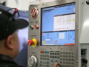
This is not meant to be an all-inclusive explanation of CNC Machining, or CNC G code programming. It is meant to be a very basic primer. A first step to get you started on a pathway to a better understanding of CNC programming.
We include a downloadable cnc g code list & cnc m code list at the end of the article.
The most popular Cam programs in use today are Mastercam, and Gibbscam. A Cam (Computer Aided Manufacturing) package price can range anywhere from $10,000 to $15,000 for a single seat of software.
Not every company is going to be able to purchase an expensive Cam software package to generate CNC G Code for CNC machining. However, even if a company has a Cam package, it will benefit from possessing a good general knowledge of CNC G Code and M Code programming language. The knowledge will help understand what is going on in the machine you are operating. This knowledge may help to keep you safe, make you more productive, (and thereby more valuable and highly paid) or it may help you get a better job.
CNC Machining programs can consist of anywhere from a few lines of G code for a simple job, to thousands of lines of CNC G code for a larger job. In this article we will focus on the simple, and shorter version.
CNC Machining programs usually will have N words at the beginning of lines in the program. N words may be at the beginning of every line, or they may be at the
N1
N2
N3
Sometimes you will see them as
N2
N4
N6
Or
N10
N20
N30
In every case, the purpose of the N word is simply to number the line or block of code. It is meant to help identify a specific line of G code or a block of code. This can be important! Imagine trying to track down an error in a huge program of several thousand lines of code if you had no numbering system to go by!
Other than identifying a line…the N words are ignored by the CNC machine control. Their only purpose is to be a method of identifying where you are at in the program. Think of N words as being similar to the page numbers of a book.
Often you may see a G00 or G0 (G Zero) used interchangeably. In most cases, when using a G number such as G00, G01, G02, G03, G04, etc., on up to G09, one would be able to use the single digit version of the command. Examples would be: G0, G1, G2, G3, G4, etc.. Almost all machines today will accept either this single digit version or the 2 digit version of this code. In the extremely rare case where an error is caused by a single digit version, or when in doubt, use the standard 2 digit version.
Example G00.
What follows is a basic list of the most common G Code for CNC machining with a brief explanation of it’s use/purpose. It is not meant to be a complete list. This is also not meant to be complete description of each individual G code’s use. When a G word offer’s more than one use, The most commonly used purpose to that G code. In some cases a G word has a different use for lathe or mill. Again, the most commonly used G words are:
G00 Rapid Transverse Motion
G01 Motion by a feed rate
G02 Motion in an arc clockwise
G03 Motion in an arc counter clockwise
G04 Dwell
G17 XY Plane selection
G18 XZ Plane selection
G19 YZ Plane selection
G28 Return to Machine zero for axis selected
G40 Cutter compensation Cancel
G41 2D Cutter compensation Left
G42 2D Cutter compensation Right
G43 Tool length compensation + (add to tool length offset)
G44 Tool length compensation – (subtract tool length offset)
G49 Cancels G43 G44
G50 Sets a speed limit for Constant surface speed (lathe)
G52 Set Work Coordinate system
G54 Work coordinate system #1
G55 Work coordinate system #2
G56 Work coordinate system #3
G57 Work coordinate system #4
G58 Work coordinate system #5
G59 Work coordinate system #6
G65 Macro Subroutine call
G70 Bolt Hole Circle
G71 Holt Hole Arc
G72 Bolt holes along an Angle
G73 High Speed Peck Drilling
G74 Reverse Tapping
G80 Turns off all canned cycles
G81 Drilling
G82 Spot Drilling
G83 Peck drilling
G84 Tapping cycle
G90 Calls up an absolute Co-ordinate grid system Positioning
G91 Calls up an incremental Co-ordinate grid system Positioning
G92 Set Work Coordinate system shift value -(grid shift)
G94 Feed per minute mode
G95 Feed per spindle revolution mode
G96 turns on Constant Surface Speed (lathe)
G97 Turns off Constant Surface Speed (lathe)
G98 Canned cycle initial point return
G99 Canned cycle R Plande return
M00 Program stop – Tells the CNC machine to stop in the middle of a program.
M01 Optional Program Stop – Tells the CNC machine to stop ONLY if the optional stop switch is active
M02 Program end
M03 Turns the Spindle on in a Clockwise direction
M04 Turns the Spindle on in a Counter-Clockwise direction
M05 Turns the Spindle off
M06 Tool change
M07 Optional coolant is not available on all machine configurations
M08 Turns flood coolant on
M09 Turns flood coolant off
M10 Normally used to turn 4th Axis brake on (mill)
M11 Normally used to turn 4th Axis brake off (mill)
M19 Spindle Orientation
M30 Program end and reset
M31 Chip conveyor on (forward)
M33 Chip conveyor off
M88 Turns through the spindle coolant on
M89 Turns through the spindle coolant off
M97 Calls up sub program for local program
M98 Sub Program Call
M99 Loop or return to rerun a sub program
This material may not be published, broadcast, rewritten, or redistributed. ©2021 Carlson Manufacturing, Inc